Designing Hoppers to Prevent Spoilage
To avoid microbial growth, proper design of storage vessels for dry bulk materials requires an understanding of the properties that affect material flow.
Handling solids is an integral part of many food manufacturing processes. Whether the end product is a solid or liquid, chances are good that powdered or granular materials are handled at some point in the process. Unfortunately, chances are also good that this part of the process does not operate optimally. The problems with handling solids can have a significant impact on product quality. One such problem is product degradation.
Degradation is the undesirable change of a product or ingredient. It can take many forms in food products, including moisture absorption, caking, breakage, and/or microbial growth. Microorganisms such as bacteria, fungi, algae, and amoeba may be beneficial, pathogenic, or neither. In some food processes, beneficial microorganisms are an essential part of the process. For example, the fermentation of alcoholic beverages requires yeast to convert sugar to alcohol. Similarly, lactose converts to lactic acid during the fermentation process that produces yogurt. Various cheeses require a specific bacterium to form the curd and to develop the flavors and textures for which they are known.
Microorganisms that are considered pathogenic are capable of causing disease or illness and must be carefully controlled and monitored throughout the food manufacturing process. Recent outbreaks of Escherichia coli O157:H7, Salmonella, and Listeria monocytogenes have caused illness and in some cases loss of life. The potential financial impact of this type of outbreak on a food manufacturing company cannot be ignored. As an example, a Salmonella contamination of peanuts and peanut products may end up costing the U.S. peanut industry $1 billion, according to the Georgia Peanut Commission (Vending Times, 2009). This Salmonella outbreak, which began in late 2008, has affected hundreds of companies and led to the recall of more than 3,900 products from crackers to ice cream. The Centers for Disease Control and Prevention (CDC) reports that 529 people in 43 states became ill after eating contaminated peanut products (CDC, 2009). This widespread recall led to the demise of the Peanut Corporation of America and resulted in its bankruptcy filing in February 2009.
In recent years, similar outbreaks have been tied to spinach, pistachios, alfalfa sprouts, and numerous other products. The potential for the presence of pathogenic microorganisms exists in virtually all food products. Manufacturers respond to this risk by employing good manufacturing practices; carefully managing their supply chain; and screening materials, ingredients, and finished products for common pathogens. Many factors affect the growth of microorganisms in food processing environments, including the source of contamination, moisture, nutrients, pH, oxidation-reduction potential, temperature, presence or absence of inhibitors, interactions between microorganisms in a population, and time (Ryser and Elmer, 2007). Some of these factors are a function of attributes that may be difficult to control, such as the presence of moisture or nutrients, the source of the material, or the cleanliness of the water used for irrigation of crops (FDA, 2009). Some factors are a matter of process control, such as avoiding temperatures or pH levels that would allow microorganisms to flourish. Others factors can be controlled or influenced by design of processing equipment and plant sanitation practices.
One factor that can be influenced by the design of equipment and process is time. Time is an important factor in the growth of microorganisms since the growth rate of mature microorganisms is typically exponential when conditions are not limiting. Thus, where growth conditions may occur, it is important to limit the duration of exposure. In some processes, a product may pass through a temperature/moisture condition that is well-suited for microbial growth. If the product has the potential to enter the process with some level of contamination (as may be the case with some agricultural products), it is particularly important to limit the residence time at these conditions to avoid excessive populations of potentially harmful microorganisms.
--- PAGE BREAK ---
Even in less-than-ideal growth conditions, populations of microorganisms can increase. This is particularly true for in-process materials that may not beas shelf stable as finished products. Thus, it is essential to maintain positive control of movement of the product through the process. When handling powdered or other dry materials in bulk form, maintaining this positive control through the process can be difficult. To accomplish this, stagnant regions and buildup where microbial growth can flourish must be eliminated.
Stagnant regions can occur at many points in a process, including on conveyors, feeders, transfer chutes, product scrubbers, mills, or dryers. Often the stagnant material may be visible, such as the buildup that might be seen in a transfer chute or a mill. In other cases, it may not be possible to see the stagnant material because of the design of the equipment. For example, screw conveyors and feeders frequently leave a stagnant layer of material between the flight tip and the trough. If not designed properly, hoppers can have stagnant material along the walls that may not be evident from the top surface. Storage vessels (silos, surge hoppers, storage bins, intermediate bulk containers, and so on) are of particular concern because a relatively large volume of material may be stagnant for a long period of time. A properly designed storage and discharge system for food applications must provide a first-in, first-out flow sequence that eliminates stagnant regions. Accomplishing this requires an understanding of how bulk solids behave during storage and flow.
Definition of a Bulk Solid
Fundamentally, a bulk solid can be defined as a group of discrete particles of any size or shape in which stress is transferred particle to particle and between particles and the containing vessel through frictional forces rather than viscous forces. Bulk solids include a wide range of materials that can behave very differently. Fine powders such as flour, powdered sugar, and baking powder may exhibit solids-gas interactions that make them prone to flooding, fluidization, or a reduced feed rate. Large particles, particularly those that are irregularly shaped (such as breakfast cereals, corn chips, or leafy vegetables) may form interlocking structures or align in a storage vessel, making discharge difficult. Some materials such as brown sugar, baking powder, and raisins are prone to arching or ratholing as a result of their cohesive strength. Blended soup mixes and breakfast cereals are often prone to de-mixing (segregation or stratification) during storage and transfer. These bulk solids follow fundamental behaviors that, when understood, can be used to design equipment that will function reliably, eliminate stagnant regions, and minimize product degradation.
Storage Vessel Flow Patterns
Two primary flow patterns can develop in a storage vessel: funnel flow and mass flow (see Figure 1). In funnel flow, an active flow channel forms above the outlet with non-flowing material at the periphery. As the level of material decreases, stagnant material in the periphery may not slide into the flowing channel if the material has sufficient cohesive strength. This can result in the formation of stable ratholes, requiring an operator to break loose the stagnant material in order to completely empty the vessel. Operator involvement creates an opportunity for product contamination as operator intervention can introduce harmful bacteria. In addition, a funnel flow discharge pattern provides a first-in, last-out flow sequence, which promotes microbial growth since the residence time in the storage vessel is uncontrolled unless the vessel is completely emptied and cleaned on a regular basis.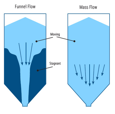
In mass flow, all of the material is in motion whenever any is withdrawn from the hopper. Material from the center as well as the periphery moves toward the outlet. A mass flow discharge pattern provides a first-in, first-out flow sequence that maximizes control of the residence time in the vessel. Mass flow vessels provide other benefits over funnel flow hoppers for food processes: A mass flow discharge pattern will eliminate stagnant regions and diminish the effects of sifting segregation (separation of large and small particles) that may occur as a vessel fills. Mass flow also provides a steady discharge at a consistent bulk density and a flow that is uniform and well-controlled. For these reasons, mass flow is advantageous for nearly all food processing applications.
--- PAGE BREAK ---
Achieving mass flow requires the following:
• ensuring that hopper walls are sufficiently smooth and steep enough to allow flow of the bulk solid along them;
• sizing the vessel outlet large enough to prevent arching; and
• ensuring withdrawal of material from the entire outlet area.
These requirements can be met by utilizing a scientific method of quantifying relevant properties of the bulk solid that dictate its behavior and applying the measured properties of the material as the basis for design.
Wall Friction and Mass Flow Hopper Angles
In order to achieve mass flow, hopper walls must be steep enough and have sufficiently low friction to allow the material to flow along them. For a given hopper geometry and wall angle, friction between the particles and the wall surface determines whether a vessel will discharge in mass flow or funnel flow. Wall friction can be affected by wall material and surface finish, properties of the bulk solid, hopper geometry, and operating conditions. In order to achieve mass flow, the bulk material must slide on the surface of the hopper, so friction between the two must be overcome by gravity. This friction is typically measured using a shear tester (see Figure 2) (ASTM International, 2006). First, the bulk solid is placed in a retaining ring on a flat coupon of wall material. Then various forces are applied to the bulk solid through the cover in a direction normal (perpendicular) to the wall coupon. The bulk solid in the ring is forced to slide along the stationary wall coupon, and the resulting shear force is measured as the applied normal force is varied.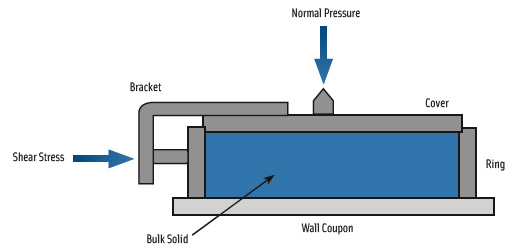
Figure 3 shows the results of a typical wall friction test. Along the horizontal axis are values of normal pressure applied to the material while the vertical axis represents the measured shear stresses required to overcome friction with the wall sample. This relationship, called the wall yield locus (WYL), is often slightly concave downward and may have a positive y-intercept. Wall friction angle, designated as ф’, is defined as the angle formed by a line drawn from the origin to a point on the WYL. For example, at the pressure σ A, the corresponding shear stress is τA, and the resulting wall friction angle is ф’A. Higher wall friction angles indicate a greater tendency for the material to adhere to a wall surface.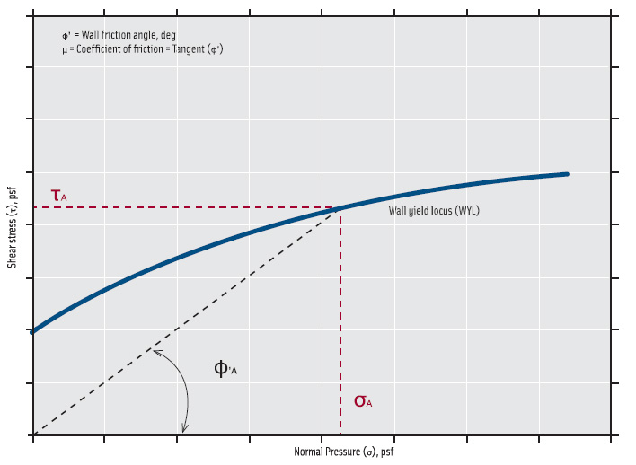
With measured values of ф’, the hopper angle required to provide mass flow can be determined using design charts that were originally developed by Andrew Jenike (Jenike, 1964). These charts indicate allowable hopper angles for mass flow when the wall friction angle is known. The required angle is dependent on the geometry of the hopper (for example, conical or wedge-shaped) and the angle of internal friction of the solid.
Figure 4 shows one chart for a conical hopper. Along the horizontal axis are values of hopper angles, Өc, measured in degrees from vertical while the vertical axis contains wall friction angles, ф’. A design solution that lies in the lower left portion of the chart will discharge in a mass flow pattern whereas a design solution that lies in the upper right portion of the chart will discharge in a funnel flow pattern. Hence, a hopper that provides a mass flow discharge pattern for one material may discharge in funnel flow if a more frictional material is placed into it.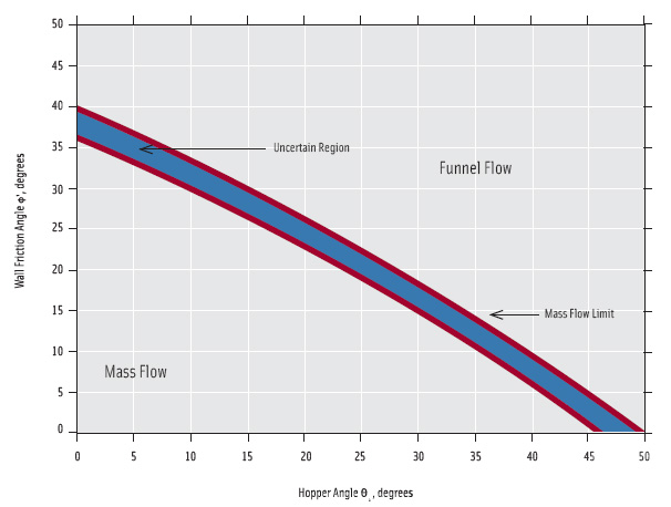
--- PAGE BREAK ---
There is a region labeled “uncertain,” which lies between funnel flow and mass flow, slightly below and to the left of the mass flow limit. This represents a margin of safety to allow for small variations in material properties, wall surfaces, and fabrication tolerances. If the design point is too close to the mass flow limit, the flow pattern may vacillate between mass flow and funnel flow, resulting in erratic discharge behavior.
Cohesive Strength and Minimum Hopper Outlet Size
Subjecting a bulk solid to consolidating pressure may result in an increase in its cohesive strength. A cohesive material gains strength under increasing consolidating pressure as would a snowball. The more tightly the snow is compacted, the greater the strength of the resulting snowball even after the compaction pressure is removed. Dry sand, which is typically free flowing, does not behave in this way and shows little to no strength gain when consolidated. It is therefore described as a free-flowing material. These are subjective terms that describe the material relative to how it is handled.
Identical materials are sometimes described as free-flowing in one process, in which flow problems are not experienced, and as cohesive in another process, in which erratic flow is observed. Despite there being no discrete delineation between these two behaviors, an objective method exists for measuring the cohesive strength of the material and for applying the results to prevent flow obstructions. Arching and ratholing are common flow obstructions that can form as a result of a material’s cohesive strength (see Figure 5). Flow obstructions frequently require an operator to access a storage or surge bin to re-initiate flow. Besides the opportunity of contamination this creates, it causes reliability, efficiency, and safety problems. It also produces a strong argument for the careful design of vessels and feeders to ensure reliable discharge.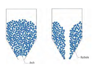
The cohesive strength of a bulk solid is a function of consolidation pressure and can be determined by the method described in ASTM D-6128 (ASTM International, 2006). A sample of powder is placed in a split cell and then brought to a known state of stress by exerting both normal and shear stresses onto the sample. This step simulates a consolidation state that would exist within a hopper during flow. Next, the shear step is conducted so that the vertical load is replaced with a smaller load, and the sample is again sheared until it fails. The pre-shear and shear steps are repeated using the same normal load for pre-shear and applying varying normal loads during shear.
Plotting the failure shear stress against normal stress then develops a yield locus. A yield locus describes the strength of the material at a particular state of consolidation. This test is repeated, developing yield loci at several consolidation states. From each yield locus, the major consolidation pressure and unconfined yield strength are determined (ASTM International, 2006). By plotting the unconfined yield strength as a function of the major consolidation pressure, the flow function of a material can be plotted. A flow function is the relationship between consolidation pressure and the cohesive strength of a bulk solid.
The greater the cohesive strength of a material, the greater will be its tendency to form a stable obstruction: an arch at the vessel outlet or a rathole in a funnel flow vessel. A stable cohesive arch is formed when the strength of the bulk solid is greater than the stresses acting to break it. The magnitude of these stresses depends on the material’s bulk density, the outlet dimension, and the geometry of the hopper (Jenike, 1964). The stresses acting to overcome a cohesive arch and cause flow are described by a hopper’s flow factor, which is a function of the internal friction of the bulk solid, the hopper angle, and the wall friction (Jenike, 1964). By measuring a material’s cohesive strength, one can calculate the minimum outlet dimension for a hopper that will prevent the formation of an arch or a rathole.
--- PAGE BREAK ---
Feeder Below Hopper
Even the most carefully designed hopper can discharge in funnel flow if the feeder does not provide uniform withdrawal of material from the entire hopper outlet. This is the case even if the outlet is large enough to prevent arching and the walls are steep enough and smooth enough to allow flow along them. This problem frequently comes up when a gate or valve is used at a hopper outlet in an attempt to regulate flow. To use a gate to regulate flow, the gate must be operated partially closed. This is detrimental to reliable flow because it prevents discharge from a portion of the hopper outlet, potentially resulting in a large volume of stagnant material in the hopper.
A feeder is normally used to control the discharge rate from a storage vessel. Many types of feeders are commonly used in food processing applications, including rotary valves, screw feeders, belt feeders, and others. Ultimately, a feeder should accomplish the following:
• Provide reliable and uninterrupted flow of material from the vessel.
• Control discharge rate from a vessel, achieving the required rate while preventing flooding.
• Remove material from the entire cross section of the hopper outlet to avoid interfering with mass flow from the vessel (Carson, 2000).
In summary, with the constant concern of microbial contamination of processed food products, proper storage vessel design for dry bulk materials should be carefully evaluated. Stagnant regions should be eliminated and a first-in, first-out flow sequence should be used. This can only be accomplished by measuring the flow properties of the materials, including cohesive strength and wall friction. These measured properties can then be used in a systematic design process to ensure that the storage vessel and feeder will operate as intended to minimize any impact on product quality.
by Scott A. Clement, a Professional Member of IFT, is Senior Project Engineer with Jenike & Johanson Inc., 3485 Empresa Dr., San Luis Obispo, Calif. ([email protected]).
by Jairo A. Paternina Gonzalez is Project Engineer, Jenike & Johanson, 400 Business Park Dr., Tyngsboro, Mass. ([email protected]).
by Carrie Hartford is Project Engineer with Jenike & Johanson Inc., San Luis Obispo, Calif. ([email protected]).
References
ASTM International. 2006. Standard test method for shear testing of bulk solids using the Jenike shear cell. ASTM D-6128.
Carson, J.W. 2000. Step-by-step process in selecting a feeder. In “Chemical Processing: Powder & Solids Annual,” pp. 38-41.
CDC. 2009. Multistate outbreak of Salmonella infections associated with peanut butter and peanut butter containing products—United States, 2008-2009. Centers for Disease Control and Prevention, MMWR Morb. Mortal. Wkly. Rep. 58: 85–90.
FDA. 2009. Production practices as risk factors in microbial food safety of fresh and fresh-cut produce. Chapt. II in “Analysis and evaluation of preventive control measures for the control and reduction/elimination of microbial hazards on fresh and freshcut produce.” U.S. Food and Drug Administration. Available at: http://www.fda.gov/Food/ScienceResearch/ResearchAreas/SafePracticesforFoodProcesses/ucm090977.htm. Accessed Feb. 22, 2010.
Jenike, A.W. 1964. Storage and flow of solids. Bulletin of the University of Utah 53(26): 28–32, 85–107.
Ryser, E.T. and Elmer, M.H. 2007. “Listeria, Listeriosis, and Food Safety,” 3rd ed. CRC Press, Boca Raton, Fla.
Vending Times. 2009. Peanut recall could cost $1B. 49(4). Available at: http://www.vendingtimes.com/ME2/dirmod.asp?sid=&nm=Article+Archives&type=Publishing&mod=Publications%3A%3AArticle&mid=8F3A7027421841978F18BE895F87F791&tier=4&id=E06E119459014347A4C9E8559CD86218. Accessed Feb. 22, 2010.
